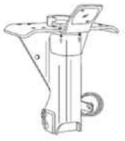
6.4.2 Uncoupling Tractor-Semitrailers

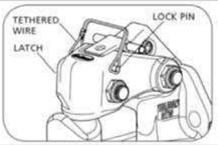
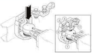
The following steps will help you to uncouple safely.

Step 1. Position Rig
  • Make sure surface of parking area can support weight of trailer.
  • Have tractor lined up with the trailer. (Pull­ing out at an angle can damage landing gear.)
Step 2. Ease Pressure on Locking Jaws
  • Shut off trailer air supply to lock trailer brakes.
  • Ease pressure on fifth wheel locking jaws by backing up gently. (This will help you release the fifth wheel locking lever.)
  • Put parking brakes on while tractor is pushing against the kingpin. (This will hold rig with pressure off the locking jaws.)
Step 3. Chock Trailer Wheels
  • Chock the trailer wheels if the trailer doesn't have spring brakes or if you're not sure. (The air could leak out of the trailer air tank, releasing its emergency brakes. Without chocks, the trailer could move.)
Step 4. Lower the Landing Gear
  • If trailer is empty, lower the landing gear until it makes firm contact with the ground.
  • If trailer is loaded, after the landing gear makes firm contact with the ground, tum crank in low gear a few extra turns. This will lift some weight off the tractor. (Do not lift trailer off the fifth wheel.) This will:
    • Make it easier to unlatch fifth wheel.
    • Make it easier to couple next time.
Step 5. Disconnect Air Lines and Electrical Cable
  • Disconnect air lines from trailer. Connect air line glad hands to dummy couplers at back of cab or couple them together.
  • Hang electrical cable with plug down to prevent moisture from entering it.
  • Make sure lines are supported so they won't be damaged while driving the tractor.
Step 6. Unlock Fifth Wheel
  • Raise the release handle lock.
  • Pull the release handle to "open" position.
  • Keep legs and feet clear of the rear tractor wheels to avoid serious injury in case the vehicle moves.
Step 7. Pull Tractor Partially Clear of Trailer
  • Pull tractor forward until fifth wheel comes out from under the trailer.
  • Stop with tractor frame under trailer (prevents trailer from falling to ground if landing gear should collapse or sink).
Step 8. Secure Tractor
  • Apply parking brake.
  • Place transmission in neutral.
Step 9. Inspect Trailer Supports
  • Make sure ground is supporting trailer.
  • Make sure landing gear is not damaged.
Step 10. Pull Tractor Clear of Trailer
  • Release parking brakes.
  • Check the area and drive tractor forward until it clears.
The lock pin is on the right side and is holding the tethered wire with the latch on the opposite side
Caption
Figure 16

6.4.3 Coupling a Pintle Hook

Step 1. Inspect Pintle Hook
  • Before operating, check for worn, damaged, or missing parts, and make sure mount is secure.
  • If the pintle hook is not secured to the mount­ing surface, the pintle hook could separate from the vehicle which, if not avoided, could result in death or serious injury.
Hook body is at the back, with the lock seat above it and the lock in front of it, attached via the lock handle with the latch at the front
Caption
Figure 17
Step 2. Unlock Lock Pin and Open Latch
  • Unlock and remove the tethered lock pin, if applicable (Figure 16).
  • Lift the lock handle away from the vehicle until the lock clears the lock seat on the hook body.
  • Open the latch by rotating the latch assembly up toward the vehicle until the latch is in its most upright position, then release the lock handle. (Figure 17 and 18)
Step 3. Lower Drawbar into Place
  • Position the drawbar eye over the horn of the pintle hook and lower it into place.
The mechanism will be lifted up with the horm beneath and the lock handle above
Caption
Figure 18
Step 4. Lock Pintle Hook
  • Push the latch closed. When correctly locked, the lock handle will rotate and move up until it is flush with the top of the latch (Figure 19).
  • Insert the tethered lock pin through the latch and lock holes, and close the tethered wire lock pin, if applicable (Figure 16).
  • Failure to correctly lock the latch can result in separation of the trailer and vehicle which, if not avoided, could result in death or seri­ous injury.
The lock handle is flush with the top of the latch and the horn is underneath
Caption
Figure 19

6.4.4 Uncoupling a Pintle Hook

Step 1. Park on Level Surface
  • Park the trailer on a firm level surface and block trailer tires.
Step 2. Disconnect Electrical Connector, Breakaway Brake Switch and Safety Chains
  • Disconnect electrical connector.
  • Disconnect breakaway brake switch lanyard.
  • Disconnect safety chains from tow vehicle.
Step 3. Unlock the Coupler
  • Unlock the coupler and open it.
Step 4. Check Ground Surface for Correct Support
  • Before extending jack, make certain the ground surface below the jack pad will support the tongue load.
Step 5. Rotate Jack Handle
  • Rotate jack handle to extend the jack and transfer the weight of the trailer tongue to the jack.
Step 6. Raise Trailer Coupler
  • Raise the trailer coupler above the tow vehicle hitch.
Step 7. Drive Forward
  • Drive tow vehicle forward.
Coupling up: long description in text
Caption
Coupling up

6.4.5 Coupling a Drawbar

Step 1. Remove Safety Lock screw and Rotate Safety Cover Bar
  • Remove safety lock screw (2), recover and keep the relative self-locking nut (12) aside then also loosen safety lock screw (2a) and turn out the adjustment screw (3) by at least five turns.
  • Rotate the safety cover bar (4) outwards so that it is completely open.
Step 2. Reverse Truck
  • Reverse truck very slowly until the ball cup drawbar eye (6) is in position exactly above the drawbar coupling ball (5).
Step 3. Lower the Drawbeam
  • Lower the drawbeam until the ball cup drawbar eye (6) lies completely covering the drawbar coupling ball (5).
Adjusting the adjustment screw: long description in text
Step 4. Rotate the Safety Cover Bar
  • Rotate the safety cover bar back inwards (4) and fit in safety lock screw (2) together with its self-locking nut.
  • Tighten in both the lock screws (2, 2a) to­gether with their relative self-locking nuts (12, 12a) at a 350 to 400 Nm torque wrench setting.
Step 5. Adjust the Adjustment Screw
  • Adjust the adjustment screw (3) until a 0.3 to 0.5 mm vertical clearance between the guard disk (13) and the ball cup (6) is reached. Lock setting with counter nut (11).
  • In the event that the safety cover bar (4) will not perfectly lodge into its seating appropri­ately, travel is strictly forbidden.
Protect coupling ball and anchor edge onto ball, long description in text
Step 6. Protect Coupling Ball and Anchor Edge onto Ball
  • Protect the part that is still visible of the cou­pling ball (5) with the rubber dust proof bellows protection cover (7). Accurately anchor the edge directly onto the ball itself.
Step 7. Lubricate the Drawbar Eye
  • Lubricate the inside of the drawbar eye ball cup (6) directly through the grease nipple (18).

 6.4.6 Uncoupling a Drawbar

Step 1. Turn Trailer Brake On
  • Make sure that the trailer brake is on.
Step 2. Remove Cover and Loosen Screws
  • Remove the rubber dust proof bellows protection cover (7).
  • Loosen the adjustment screw (3) and the counter nut (11).
  • Loosen safety lock screw (2a) and remove safety lock screw (2) together with its self­-locking nut (12).
Step 3. Rotate Safety Cover Bar and Lift Trailer Drawbeam
  • Rotate the safety cover bar (4) outwards so that it is completely open.
  • Lift the trailer drawbeam until the drawbar coupling ball (5) is fully visible, then travel forward with the trailer very slowly.
  • Rotate the safety cover bar inwards (4) until it lodges back in its housing.
Step 4. Lock Safety Screw and Tighten Self-Locking Nut
  • Fit in safety lock screw (2) and tighten in self-locking nut (12).          

6.4.7 - Coupling a Gooseneck Hitch

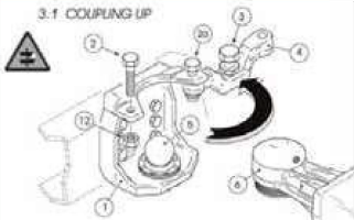
If you are hooking up a Gooseneck or a fifth wheel hitch, the procedure is a little different from a receiver and ball, but it is not more difficult.

Step 1. Open the Latch and Lubricate the Gooseneck Ball
  • Open the clamp latch on the Gooseneck coupler.
  • Make sure that the Gooseneck ball is properly lubricated.
Step 2. Position Coupler and Latch the Clamp
  • Position the trailer's coupler directly over the ball and lower the Gooseneck trailer into position and latch the clamp.
Step 3. Attach Safety Chains
  • Attach your safety chains. Remember that all trailers are required by law to have safety chains.
Step 4. Connect Trailer Light Wiring
  • Connect your trailer light wiring to your ve­hicle's connector.
  • Check all of your lights, including your brake lights.
Step 5. Lower and Stow the Trailer Jacks
  • Completely lower and stow the trailer jacks, allowing the weight to settle onto the tow vehicle.
Install safety pin and clip, long description in text

6.4.8 - Uncoupling a Gooseneck Hitch

Step 1. Remove Safety Pin and Clip
  • Simply remove safety pin and clip.
Step 2. Rotate Handle and Raise Trailer Off Ball
  • Rotate handle to this position (Fig. B) and raise trailer off ball. Coupler will return to load position automatically.
Step 3. Install Safety Pin and Clip
  • Install safety pin and clip. (Fig. B)